
John has been researching ancient practices for turning instrument pegs. I thought his research was quite interesting. Here it is, reproduced with his permission. Enjoy...
_________________
Making Pegs
by John Downing
My method of making pegs is to use two stage profile cutters set in a metal turning lathe - the lead screw and cross slide being hand operated during the cutting process. This set up allows me to quickly produce peg blanks of reasonably consistent size and shank diameter. Any additional fine detail required is done by hand - with the peg blank still in the lathe - using small turning chisels.
The image below shows some examples of the pegs made using this method. From left to right - a standard commercially available rosewood violin peg (for comparison purposes) - an ebony peg from a copy of an early 19th C guitar by Grobert, a boxwood lute peg cut down for a 4 course guitar, a boxwood vihuela peg, and two lute pegs - one in Brazilian rosewood, the other in stained boxwood. Below are examples of some of my profile cutters used to make these pegs - made from tool steel, hand filed to the required profile, hardened and tempered.

The images below show the cutting sequence to produce a peg blank. (I am not cutting pegs at present so am here using a finished lute peg blank to demonstrate).
The cutter is first moved from right to left to rough shape and reduce the diameter of the billet of wood from which the peg is to be turned. When the required shank diameter is close to that required, a small trial cut at the right side is made and the diameter measured with calipers (with the lathe switched off!!). If the diameter is correct, the cutter is traversed fully to the left taking a light final cut over the length of the peg shank. At the end of this traverse the cutter automatically forms the required profile of one half of the peg head. At this point the cutter is moved inwards slightly to form a relief groove on the peg shank just under the peghead. The cutter is then withdrawn, traversed further to the left and moved back into the work again to automatically form the other side of the peghead.
For this example of peg style the peg head was undercut by hand using a small turning chisel. If a collar is required on a peg shank this is produced by raising the cutter the required amount, continuing the traverse the required distance and then feeding the cutter back into the work.
I always turn the shanks parallel using a peg shaper to later produce the required taper.
I choose to make the cutters to operate in two stages because they are a bit easier to make than a single action cutter and also reduce the cutting forces necessary. The sharp pointed section of the cutter also does most of the cutting work. The cutting action is by scraping which is not ideal but by using hard close grained woods like boxwood, setting the cutter at the correct height and running the lathe at maximum speed satisfactory results can be achieved leaving only a small amount of hand finishing.
The cutters must, of course, be kept sharp by honing the upper face only on an oil stone.

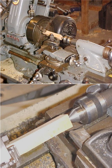
Here is my lathe with a billet of boxwood mounted in a 4 jaw chuck ready for turning into a peg. I cut the billets to the same size rectangular cross section to facilitate centering in the chuck. Once a billet has been centered in the chuck it is then only necessary to release two of the chuck jaws when changing billets to maintain correct centering. Provided there is sufficient material allowance on the billets, precise centering is not crucial. Once held in the chuck, the other end of the billet is supported by a live centre mounted in the lathe tailstock for additional support. The centre is simply wound in to form its own indentation in the billet.
Peg blanks are finished by first forming the two faces of the peg head. I just cut them flat with a chisel used freehand and by eye as this is how most of the pegs on early instruments were made. The peg head is then carefully sanded to remove any machining marks and round off any sharp edges.
Needless to say, a lathe is required to make pegs this way.
Commercially available, mass produced violin pegs are often of high quality and relatively low cost. These are by far the best option if you do not have the necessary equipment or desire to make your own pegs. In fact once you figure in your time and material costs it is impossible to beat commercial violin pegs for price.

No question about it - hand carving of pegs is a perfectly viable option and can yield results impossible to achieve by any machining process. I also have made pegs this way when I had no other 'quick and easy' alternative'. I have also made pegs built up from individually cut components glued together with high strength epoxy glue.
Replica pegs that I made in this manner - copies of those shown on the lute in the 16th 'Ambassadors" painting by Hans Holbein were made this way. The balls were formed on a lathe (yes - with a profile cutter) and then glued to a separately turned peg shank. The pegs were made in rosewood and worked well without failure - although , no doubt, in the 16th C the pegs would have been carved individually from a solid piece of wood. I do not have any images of these pegs as I gave the instrument to a friend in the USA many years ago but the attached image of the Holbein lute shows how they looked.

The principle of the very simplest form of lathe - the bow or pole lathe - might be adapted for peg turning and can easily be made at very low cost. It would require a bit of practice to operate but as this type of lathe was once used by watchmakers as well as other craftsmen for accurately turning small work it is well adapted for peg making.
This type of lathe has no moving parts and does not require an electric motor drive. The wooden peg blank (roughly cut to a hexagonal cross section) is mounted between two fixed centres (pointed bolts or woodscrews mounted in a wooden frame) with a cord wrapped a couple of times around the work itself. The cord can be the string of a bow or connected at one end to a springy overhead pole (or a metal spring) and at the other to a foot operated treadle. In the bow operated lathe the action of the bow causes the work to rotate between centres - first in one direction and then the other. The turning chisel - held in the other hand supported on a fixed tool rest - can only cut when the work is rotating towards the operator. Clearly with the bow being operated with one hand and the other being used to hold the cutting tool it must take a bit of practice to get everything coordinated to produce consistent work. The foot operated pole arrangement is an improvement as it frees the operator's hands to control the cutting tool - although cuts can still only be made when the work is rotating towards the operator.
I have not tried it but I will and know that it will work. Isn't early, "primitive" technology wonderful!
Below are some rather quaint engravings from "Mechanick Exercises or the Doctrine of Handy-Works" by Joseph Moxon, 1703 but clearly show the principles involved.

As I have an interest in early technologies and was curious to find out if a simple, easy to make, small bow lathe could be used to make oud or lute pegs, I decided to do a bit of"hands on" research. Therefore, yesterday afternoon I created a small bow lathe. I didn't want to spend a lot of time so no drawings were made for the project - it was just made up by eye ("if it looks right it is right" design philosophy) from scrap materials lying about in my workshop.
The 'bedplate' was cut from a piece of 3/4" thick pine about 4 inches wide and 11 inches long. The end blocks holding the centres were made from 2 inch thick Elm wood (elm resists splitting so is good for this application but most hardwoods would do). The head blocks were drilled together to maintain good alignment of the centre holes (but this is not critical in this type of lathe). The tool rest was made from a piece of maple bolted to a pine "cross slide" so that it could be set at any position relative to the work piece. The height of the tool rest is currently fixed at about 3/16 inch below the centres - but this might require adjustment later. A cutout was made in the front of the 'bed plate' (an afterthought!) to allow the cross slide assembly full access for positioning the tool rest.
A 3 inch square by 1 inch thick block of pine was fitted below the 'bed plate' so that the lathe could be conveniently and firmly mounted in a bench vise. Alternatively the lathe could simply be screwed to a workbench.
The fixed centres were made from 3/8 inch screwed bar - each about 3 1/2 inches long. The points of about 60 degree angle were made by mounting the screwed bar in a drill chuck and by holding the rotating piece at the required angle against a grind stone. A slot was cut in the opposite end with a hacksaw so that each centre could be adjusted with a screwdriver.
I used a machinist tap to cut a thread for the centres in each head block to give a more positive mounting and adjustment for the centres but this is not absolutely necessary - a close clearance hole would do just as well. Each centre is locked in place with a nut and washer on each side of each head block.
This particular design gives a distance between centres of about 5 inches which should cover most peg requirements.

The 'motive power' provided for the lathe - the bow - was made a bit like a violin (or rather double bass!) bow from a piece of ash wood (but most woods could be used for this) around 34 inches long by about 1/4 inch thick and 1 1/4 inch wide tapering to about 5/8 inch at the tip. The tip end was curved by hot bending and a pine block about 3 inches deep was fitted at the 'handle ' end. A simple 'archers' bow design would likely do just as well.
A saw cut was made in the underside of the block so that the bow string could be easily released and the string tension adjusted according to the size of the workpiece diameter with knots tied along the string length. The operating string length is about 24 inches.
Now for some trials .......................... !!

Can a simple bow lathe be used for turning oud pegs?
In volume 4 of the five volume 19th C monumental work on the lathe by John Jacob Holzapffel, the author describes such a lathe as used by "the Arabian and Moslem group of turners in the numerous turners shops in Cairo" (1873). Holzapffel writes " The Arab turner works nearly as much in public as the Indian, his workshop being a small square room, the front entirely open to the street, with the floor upon which he sits about three feet above the level of the road. He, also, will carry his lathe to his work, and it is his daily practice, when the sun shines too powerfully, to quit his workshop, and carrying his lathe over to the opposite and shady side of the street, to establish himself on the ground in front of the shop of one of his neighbours ......... The lathe, although of so rough a description, has been most effectively employed for centuries, for the production of a peculiar and very beautiful ornamental wood work, for the interior decoration of Mosques and houses, for screens, seats and other objects, and for the Arabian lattice windows called "Meshrebeeyeh". These oriel windows, have all those portions which are usually of glass, entirely filled by open, turned, wooden latticework, formed of an infinite number of small turned pieces ..... The skilful handicraft displayed in these constructions, especially when viewed in connection with the simple tools employed, is so remarkable, as to merit a short notice"
The engraving shows the Arabic bow lathe, a 'steady' used to prevent flexing of long cylindrical work pieces when being turned and a variation of the bow - the cord being first wrapped around a hinged handle which is then folded back to produce the required tension.

I found some time this afternoon to run some turning trials with the bow lathe. My material for the test was boxwood - close grained, bone dry and very hard - cut into a billet 3/4 inch square with the corners dressed off with a plane to form a hexagonal section. This is how I would usually prepare a turning blank for use in a conventional wood or metal turning lathe.
An indentation was made in the centre of each end with an pointed scriber and the billet mounted between the lathe centres so that it would rotate freely but without any 'end play'.
The centres were locked up with the lock nuts on either side so that they could not rotate or work loose.
The bow string was wrapped once around the work at one end so that when the bow was pulled the work rotated towards the tool rest. I found it best to stand behind the lathe (mounted in a bench vise) pulling the bow towards me (the power stroke) leaning over the lathe to manipulate the cutting tool on the tool rest. Pushing the bow for a power stroke tends to flex the bow tip causing the string to slacken and slip so this motion should only be used for the return stroke. As the bow string tends to wander off the work it is best to cut a groove for the string at one end of the work - the work then becoming a high speed pulley - and to operate the bow at an angle to the work to prevent this problem which can occur even when there is a groove. The larger the diameter of the work the higher the torque and more 'powerful' the cutting force but with fewer rotations of the work per bow stroke. The speed of rotation depends also upon how quickly the bow is moved so can be finely controlled by the operator.
Each power stroke should be made deliberately after the tool has been correctly positioned - do not work the bow quickly back and forth as if sawing a piece of wood.
First attempts to turn this rough billet were not completely successful as the tool tended to catch on the corners and jam the work. Once a section had been rounded off, however, it was possible to progress.
For the second trial I decided to first read what Joseph Moxon had to say in 1703. No point in re-inventing the wheel ....... !!

This is what Moxon had to say about turning hard woods on a bow lathe:
" If the wood be very hard, as Ebony, Lignum Vitae; or if it be Ivory, Bone, or Horn they are to turn; they neither use the same tools they do for soft wood; because their edge is too tender: nor do they use their other tools as they do soft wood. For the tools made for hard wood are made with a stronger point, edge, etc than they are for soft .... and they use them differently. For hard wood, they raise the tool rest near the horizontal plane of the axis of the work, setting it as close as conveniently they can to their work, and lay the tool flat and steady upon the tool rest which being hard held in this position, does by the coming about of the work, cut or tear off all the extuberances the tool touches in the sweep of the work".
Moxon earlier in his text lists common "softwoods" for turning as Maple, Alder, Birch, Beech, Elm, Oak, Fir etc. for which cutting gouges etc are used. For turning "hard" woods he describes above the use of scraping action lathe tools. He states that the work must first be prepared for turning by rounding it off close to the required finished diameter by hewing or with a wood rasp.
Then:
"But having fitted the work into the lathe, they begin to work with the sharp-pointed grooving tool, or else with the triangular grooving tool, and with the point of either of these tools break the grain of the wood, by laying small grooves upon its surface, till they have pretty well wrought away extuberances, and brought the work tolerably near an intended shape, by straightening, hollowing, and leaving risings in their several proper places. Afterwards with edged grooving tools of a proper breadth, they cut down and smoothen away the extuberances left by the sharp pointed grooving tool and bring the work into perfect shape. Which done, they smoothen the work with the (bevelled) edge of a piece of a blade of a broken knife ... for then its sharp edge scrapes or shaves off the little roughnesses the grosser tools left upon the work."
For trial #2, I filed the billet, while still mounted in the lathe for convenience, to round section and rough profile - using a wood rasp. I reground a small wood working chisel to a sharp tip and curved profile on one side - sharpened on the top face - as an all purpose scraping tool for testing purposes. Grooves were cut in the work using the pointed tip - as described by Moxon - and then smoothed away with the curved section of the tool. This worked quite well and efficiently producing some nice fine shavings.

These images show rough shaping a peg head and shank with the scraping tool. The shank section is being smoothed off with a straight wood chisel. As this has been just a quick trial with makeshift cutting tools and as I did not want to spend more than an hour experimenting today, I just went far enough to establish that this method could be used for making pegs. I imagine that a peg could be made using this lathe technique - with the appropriate tools and some practice - from start to finish in, say, 1/2 hour per peg?
Fine sandpaper can also be used (preferably a strip glued to a narrow piece of wood) to produce the final shape and finish.
Tools can be ground from low cost High Speed Steel lathe tool blanks available from import machine tool suppliers or from old chisels or knife blades or even broken drill bits.
Now I can do it a lot faster and easier on a metal turning lathe powered by a 1 HP electric motor - once I have everything set up for a long production run - but I think that this simpler, low cost, quieter more peaceful approach could have many merits - especially when oil (and hence electricity) becomes a prohibitively expensive commodity - or if you just want to make ouds in a peaceful, remote location away from all of that!

The next obvious development of the simple fixed centre bow lathe is to substitute a hand cranked wheel instead of a bow to directly drive the work. This has the disadvantage of increasing the complexity of the tool but has the advantage of providing continuous rotation of the work, greater torque and higher speeds.
Holzapffel gives us an engraving of a watchmaker's "turns". This is even more sophisticated in that it is made of metal and dispenses with one of the fixed centres - replaced with a chuck rotating on a fixed bearing. This additional sophistication would not be necessary, however, for a fixed centre lathe dedicated to peg turning. Also the hand cranked wheel and its support could be easily and satisfactorily made from wood rather than metal.
For a post script - as I was putting together this article, I suddenly remembered that many years ago I had picked up a broken piece of old farm equipment from the local dump because it looked as though it could be useful some day (yes I have a bad habit of collecting 'junk' for eventual 'recycling!). This odd looking tool is a cast iron hand cranked grinder for sharpening the cutting blades of an agricultural sickle bar mower (a sickle bar mower cuts hay rather like a gigantic barber's hair clippers or sheep shears). This has been sitting in my "scrap" pile for about 15 years or so and it occurred to me that - with the addition of a 12 inch diameter wooden pulley bolted to the wheel - it would make a perfect hand cranked drive for my experimental bow lathe! So, I removed the broken unwanted parts and painted the wheel and support ready for the next stage which I shall accomplish some time in the future as the motivation takes me - so don't hold your breath!

This image of an Egyptian wood turner using a bow lathe may be of interest. It is an engraving from the magnificent and historically important book "Description de l'Egypte" published in 1802 on order of Napoleon Bonaparte containing hundreds of superb detailed engravings of Egyptian architecture, life, flora and fauna in the 18th C made during Bonaparte's failed military campaign in Egypt.
Note the large rasp hanging on the wall - for preliminary rough shaping of the work and the ingenious adjustable, foot controlled tool rest - pivoted at one end with a roller at the other end.
A complete modern reprint in paperback - introductory text in French, English and German - is available from Taschen
ISBN 3-8228-8964-4

- John Downing. July, 2010